Need help with simple electronics (breadboard, etc) question
So, Im making a robot without a microcontroller, on a breadboard. So far I have the timer, flip flops, and TTL logic done. I have two outputs which go to cheap DC motors. When the output is true, I need to make the motor go forward. When the output is false, I need to make the motor go backwards.
I have no training/experience with electronics. I do know that transistors can do what I want, but am not sure how - can anyone help me? The more details the better
Thank you!
Do you just need something to drive the motors? I would recomend a mosfet. I have used them on some of my own robotics projects. Radio Shack sells one, but its kind of big. I like the 2n7000 ( I think thats the #). Its smaller but gets the job done.
Do a search for B.E.A.M schematics. You should find some good sites with motor drivers.
I was just thinking I should do a post to see if anyone else had electronics as a hobby.
Mosfets are pretty simple to use. Take the output from one of your flip flops and have it drive the gate of the mosfet. It then acts like a switch.
Robot Builders Bonanza is a greatbook for robotics without micro's. It's a classic. Just about any library should be able to get it. Lots of good stuff in there.
Bipolar transistors will work also. They tend to be a little more "fussy".
If you can't find any circuits online. Let me know. I will dig through my archive and see what I can find. (collecting electronics books and magazines is a special interest of mine)
The H-bridge is the classic DC motor control circuit. Here's one: http://www.cadvision.com/blanchas/hexfet/np-s.htm
In your case you just want to, for each motor, attach your output to one of the inputs of the bridge and the inverted output to the other. You can also use an H-bridge to short circuit the motor, which acts like a brake (if both the inputs to the H-bridge both are either high or low).
Edit: You can also just buy one in an IC.
Thanks guys.
When I read the first response, and saw the diagram of an N MOSFET, I went ahead and reinvented the H Bridge :p c'est la vie!
I cant do IC form because this is for a class for high school students this summer that I am designing, and want the kids to actually understand whats going on every step of the way (a 555 timer is the only 'black box' component I am using, and Im using it to teach how to deal with black boxes!).
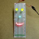
Currently my robot design is just 2 DC motors / wheels, a power source, breadboard, and two antenna which complete a circuit when bumped. As soon as an antenna is bumped, it backs up until the next clock tick, turns away from that antenna (or left, if both were bumped) until the clock tick after that, and then resumes going forward.
I should have everything figured out, and plugged into Yenka (first free electronics simulator I found; its not bad) by tomorrow. After I post my entire project and (hopefully) get a "No, your not an idiot, that'll work" I will order the parts. Yay digikey!
Im also planning to design another class using an Arduino (specifically, Really Bare Bones Arduino), but Im not sure what to make in that class. Thankfully, thats a worry for another day.
Okay so I got enough time to finish my circuit diagram and it works!
[img][800:948]http://img337.imageshack.us/img337/3936/diagram1o.png[/img]
[img][800:948]http://img812.imageshack.us/img812/4710/diagram2.png[/img]
Well, it works in the simulator, and as long as I dont turn the power off and then back on.
Whenever I flip the switch I placed right next to the 3V power source, I blow up several components:
[img][800:948]http://img834.imageshack.us/img834/7720/diagram3.png[/img]
Mousing over them shows that they were fed 1.5V above their 1V tolerance. I tried adding a resistor right before the power switch, but it seems like there is no middle ground between making the circuit not work and fixing the problem.
Any ideas?
EDIT: That odd diode on the left of the second picture is not actually there - just an error in Yenka's built in screen capture.
EDIT2: Actually, nevermind. Looking at digikey, the circuits arent actually as fragile as Yenka indicates the 7400 series were. I think Im ready to assemble a parts list
Similar Topics | |
---|---|
question |
08 Feb 2025, 7:06 am |
Work Question |
07 Mar 2025, 12:52 am |
I have a question for women 40 and over |
23 Mar 2025, 11:57 pm |
Hi my question how do you create Relationships ? |
24 Feb 2025, 11:21 am |